
Lesson 9: Camerawork
In this tutorial we look at how the "camera" in our world can be modelled and controlled, and add some basic movement using the arrow keys.
In our previous lessons, all our coordinates were in relation to the window, ranging from -1 to +1 in each axis. These are known as the Normalised Device Coordinates. But clearly trying to model an entire world in such confined coordinates is quite difficult. It's much easier to use human-intuitive scales. What we can do instead is use a natural coordinate system to build a virtual world, and then use some mathematics to transform what's visible in that world into our -1 to +1 scale window.
In this lesson we'll look at remodelling our scene in a world coordinate system. We'll add a movable camera to that world, and then cover the process of projecting that coordinate system onto our window.
To do that, we'll use a world coordinate system where the X and Y axes represent the floor plane, and Z the vertical component. There is some logic to using X and Y for the floor, as it's intuitively like reading a map of the world. Virtually every program or piece of modelling software uses a slightly different convention here about which axis represents which direction, but it doesn't matter too much as long as you pick a system and stick with it consistently in your code. We'll use a system where X represents forwards, Y to the left, and therefore following the right-hand rule, Z will be up.
Also note that we'll be transforming between various 3D coordinate systems in this lesson by using transformation matrices. If you're not comfortable with matrices or matrix multiplications, we have a special page introducing the topic here, and an introduction to using them as the primary tool for performing transformations in 3D here.
Model Space
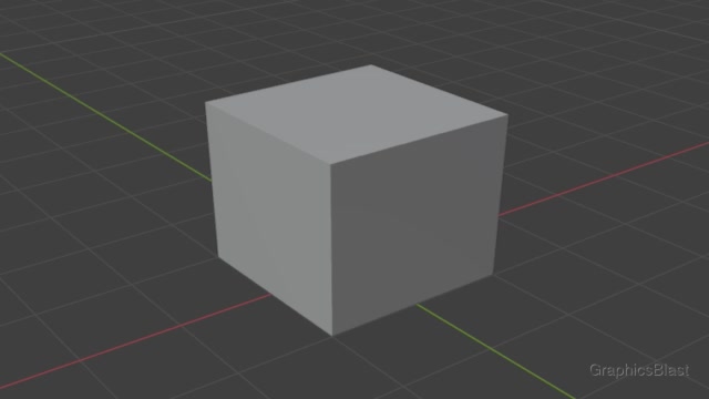
Usually any object more complex than a simple triangle or square will be modelled first in a tool like Blender. The model's vertex coordinates will be saved into a file, which our program will then read to display the model.
As the modeller will probably not know where the model should go in your virtual world, the model will (ideally) sit centred on the origin. We describe the coordinates of this model as being in model space - they are relative to the model's origin. The coordinates are centred on the x and y axes. We can imagine the z axis as representing the object's height, and therefore we imagine that a z coordinate of zero represents the floor. The object is therefore not centred on the z axis, but should just be touching the axis. For some objects, such as buildings, the models sometimes go slightly below zero in order to make sure that there are no seams or possibilities of small gaps in case the ground is not even.
World Space
To begin constructing our virtual world, we then transform each of our objects into world space. We can imagine this coordinate system as like a virtual map of the world in which our objects are to be placed.
Each of our models needs to be moved into this coordinate system. To capture all the possible ways we might need to rotate or translate or otherwise transform the model's coordinates to get them into world space, we use a transformation matrix. These are compact 2D arrays of 4x4 floats, which can capture any transformation or combination of transformations. Again we have a page dedicated to the topic if you want to get a deeper insight into how transformation matrices work. Any transformation matrix which moves vertices from model space to world space is called a model matrix.
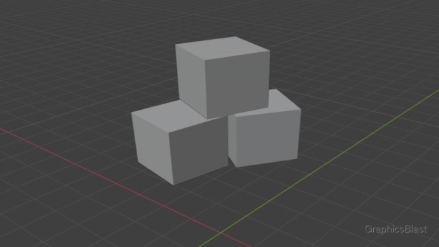
In our image examples, we originally had a box created in model space. To make that object appear three times in our world, we would need to create three model matrices, with each of these describing what transformation is necessary to move the box from being in model space (sat on the origin) to each of the three positions it appears in in our world.
What you choose to be the origin of the world space coordinate system does not matter, but usually it's easier if everything is relatively close to the origin.
We can also imagine that our camera is positioned somewhere within this world space, and is free to move around and look at anything.
Camera Space
The first step towards rendering our world is to make everything relative to the camera inside it. That is to say, we make the camera the centre of the world. Things close to the camera will now be close to the origin, and distant objects far from the origin.
We apply a single transformation to every vertex in our world, rotating and translating it so that it's now centred around the camera. This transformation matrix is known as the view matrix, in the sense of it's the camera's "view" of the world. Once it's been applied, everything in this coordinate system is described as being in camera space, or relative to the camera.
Calculating this matrix simply involves finding the transformation matrix which moves the camera from it's position in the world to the origin. As we know the camera's position and orientation in our world, it's simply a matter of encoding that as a transformation matrix.
After applying this transformation, things in front of the camera will now be in front of the origin (ie. have a positive x value). Things above the camera will be above the origin. Things far away from the camera will be far from the origin.
Clip Space
This is where the magic happens.
Once we have all our geometry in camera space, we then need to map it to Normalised Device Coordinates, the box of -1 to +1 in each axis which our window can actually display. If we have a transformation matrix which can map all the geometry in camera space which is in front of the camera to this coordinate space, we then have a way of rendering the world as the camera sees it.
That's exactly what our projection matrix does.
Projection matrices come in two main forms.
First of all there is an orthographic projection matrix, which performs this transformation keeping parallel lines orthogonal. The result is a 2D-like view of the world. There is no parallax in the camera. If we rendered a building like this, it would appear flat on screen like it would appear in a set of blueprints. The depth of the camera just decides what's drawn on top of what in this scenario.
On the other hand, a perspective projection matrix transforms things in a more traditional 3D way. Things close to the camera appear larger, and things far away small, giving us a parallax effect.
One thing to note here is that whichever type of projection matrix you use, things need to be transformed into the Normalised Device Coordinates of our window, which have a range of -1 to +1 in all axes, including the depth (Z) axis. This means there needs to be a finite minimum and maximum distance of things in our world which we can render.
To take a perspective projection matrix as an example, it could transform things up to a distance of say 100 units from the camera into the -1 to +1 range of our window, but anything beyond that distance will be outside the box and therefore not be visible. This means our camera also has a minimum and maximum render distance which cannot be avoided. We cannot render triangles at infinite distance from the camera.
These are known as the camera's clip planes, and make other pieces of the underlying maths much easier too.
We define a near clip plane, a minimum distance from our camera at which objects can be rendered, and will map to a value of Z value of +1 in our window.
If we were to set the minimum distance at which we can render objects to be zero, we would run into issues with dividing by zero, as well as various other issues, so usually we set it slightly above zero.
We don't usually want to render things extremely close to the camera anyway, as things super close will fill the whole view no matter how small they are.
Typically you will see a near clip plane value of something like 0.1.
Projection matrices also have a far clip plane, which defines the maximum distance from the camera which will be rendered, which will be mapped to a Z value of -1 in the window. Geometry beyond this won't be rendered, so if we want to render beyond that it would need to be faked somehow....we'll cover this later!
Unfortunately we cannot just set the far clip plane to some incredibly high value either to solve this problem. We would quickly approach the limit of precision of the buffers. Floating point numbers can only capture so much precision. The result of setting a far clip plane too far away is that after the GPU has transformed the geometry, it will have trouble with distant objects, deciding which triangle should be closer to the camera than the other. This leads to some really strange artefacts, so generally we limit the far clip plane to a value of something like a hundred or a thousand.
A quick technical note here.
Multiplying by the projection matrix technically brings everything into "clip space".
The resulting values are not homogeneously normalised.
This means that the 4th value of the vec4 coordinate won't equal 1.
You don't really need to worry about this, as OpenGL handles this situation automatically, but I just want to give you full disclosure and knowledge of the pipeline. When you set a vertex's position to have a non-1 value in the 4th component, OpenGL will automatically divide the vertex's x, y, z, and w (4th component) value by w to normalise it. Only after this automatic normalisation step, the vertices will lay in OpenGL's unit square (assuming they're visible to the camera), and we can say they're Normalised Device Coordinates. Before this automatic process, we say they're in clip space. This normalisation process is known as perspective division if you want to read more about it. But you really don't need to worry about this process.
Summary
To recap our transformation pipeline:
- Each model has it's coordinates centred around the origin.
- We generate a model matrix and multiply each of our model's coordinates by it to move them into world space, to position them in our virtual world.
- If we want that model to appear twice in our world, we create a second model matrix and multiply the original model's coordinates by this second model matrix to position it somewhere else in our world.
- We multiply all our vertices in world space with a view matrix to make the camera the centre of the world - camera space.
- We then multiply these coordinates by the projection matrix to apply the camera's parameters to them, moving everything in to clip space.
- OpenGL will automatically normalise the coordinates into Normalised Device Coordinates.
- Any coordinates the camera can "see" will now lie between -1 and +1 in each axis, ready to be drawn to our window.
The GLM library
We could write a set of functions ourselves which abstract the process of creating 4x4 matrices, and provide functions to multiply them together, etc.
However there is a very clean, efficient and cross-platform library available to perform this task for us, called the GLM library (GL Mathematics). It's also fast, and as the library is designed for use with OpenGL, the matrices used here can be passed directly to OpenGL/the GPU. As someone who did originally write their own functions for this, trust me, this library is a wonder. But just to make the point, it is possible to do this yourself without too much effort.
The source code for GLM is available from the library's GitHub page.
Once you have a copy of the code, setting it up is really easy. The library is entirely written as header files, so we just need to add the path to the folder containing them to our Makefile:
| 3. | OBJS = main.cpp shader.cpp |
| 4. | |
| + 5. | |
| 6. | |
| 7. | LINKER_DIRS = -LC:\SDL3_precompiled\lib -LC:\glew\lib\Release\x64 |
It's a bit hard to see, but I've added the path to GLM's headers to my INCLUDE_DIRS variable.
The library is now ready to use!
Positioning
We'll start off be including the header files for the glm library in main.cpp.
| 1. | #include "shader.h" |
| 2. | |
| 3. | #include <SDL3/SDL.h> |
| 4. | #include <SDL3/SDL_main.h> |
| 5. | #include <SDL3_image/SDL_image.h> |
| 6. | #include <GL/glew.h> |
| + 7. | |
| + 8. | |
| 9. | |
| 10. | #include <string> |
| 11. | #include <stdio.h> |
The first header imports the main library itself, giving us access to the various matrix and vector data-types in our code. Meanwhile the second header includes the type pointer functions, which give us convenient ways of passing these types directly into OpenGL.
Next, let's define a few variables we are going to need.
| 19. | bool programRunning = true; |
| 20. | bool isFullscreen = false; |
| 21. | bool useWireframe = false; |
| 22. | |
| + 23. | |
| + 24. | |
| + 25. | |
| 26. | |
| 27. | Shader mainShader; |
| 28. | |
| 29. | GLuint vao; |
| 30. | GLuint vbo[3]; |
These variables will be used to store the position of the camera within our world.
For now, our camera will be positioned at (0, 0, 0) - on the origin of our world space coordinate system.
Remember that the units of the world are whatever you want them to be. If you want your world to be based on meters, feet or light years, it doesn't matter. Just make sure that you use the same unit consistently throughout your code and models.
As we plan for our world coordinate system to have X forwards, Y to the left, and Z upwards, we need to update our rendered square's vertex coordinates. As things currently stand, they all have a Z value of zero, and vary in the other two axes, so they would be laying flat on the floor in our world.
Let's adjust them so that the square "stands-up". Remember, these are the coordinates of a model so should be in model space, centred on the origin. They'll be positioned within the world by the model matrix.
| 110. | GLfloat vertices[] = |
| 111. | { |
| + 112. | |
| + 113. | |
| + 114. | |
| + 115. | |
| 116. | }; |
The coordinates now vary along the Y and Z axes, but flat in the X. It will have some left-right dimensionality, and some up-down. If we position it in front of the camera, it will therefore be visible in the world coordinate system.
I'm also going to adjust our handleEvents function here.
I'm going to make it so that pressing the arrow keys (or "WASD") will adjust our x, y, z variables, in effect altering the camera's position allowing it to move around our world.
I'm not going to do anything fancy right now, just simply adjust the position based on which key was pressed, in effect strafing the camera around.
| 206. | else if(event.key.key == SDLK_T) |
| 207. | { |
| 208. | useWireframe = !useWireframe; |
| 209. | if(useWireframe) |
| 210. | { |
| 211. | glPolygonMode(GL_FRONT_AND_BACK, GL_LINE); |
| 212. | } |
| 213. | else |
| 214. | { |
| 215. | glPolygonMode(GL_FRONT_AND_BACK, GL_FILL); |
| 216. | } |
| 217. | } |
| + 218. | |
| + 219. | |
| + 220. | |
| + 221. | |
| 222. | ... |
We check if the user pressed either the up arrow key, or the "W" key on their keyboard. If this happens, we move the camera one unit forward, or into the X axis. Remember that in our world coordinate space, X is forwards, Y is to the left, and Z up.
Let's now do the same for the rest of the keys:
| 218. | else if(event.key.key == SDLK_W || event.key.key == SDLK_UP) |
| 219. | { |
| 220. | x += 1.0; |
| 221. | } |
| + 222. | |
| + 223. | |
| + 224. | |
| + 225. | |
| + 226. | |
| + 227. | |
| + 228. | |
| + 229. | |
| + 230. | |
| + 231. | |
| + 232. | |
| + 233. | |
| 234. | ... |
For the down or "S" key, we just do the reverse of moving forwards and subtract from the X position. When the user tries to go to the left, we add to the camera's Y position, and so therefore to go right we subtract from it.
As we have a Z coordinate for moving the camera vertically up and down, let's implement that too while we're here:
| 230. | else if(event.key.key == SDLK_D || event.key.key == SDLK_RIGHT) |
| 231. | { |
| 232. | y -= 1.0; |
| 233. | } |
| + 234. | |
| + 235. | |
| + 236. | |
| + 237. | |
| + 238. | |
| + 239. | |
| + 240. | |
| + 241. | |
| 242. | } |
| 243. | } |
| 244. | } |
In this case, I've bound these movements to the left shift and left control keys, adding and subtracting to the camera's Z coordinate to alter the camera's height above the ground.
Setting up our matrices
Now that our code contains the position of the camera within our world, and we can freely move it around, we need to actually feed that information into our shaders to make use of it. We therefore need to construct our three matrices: a model matrix to position our square model within our world, a view matrix to make the world relative to our camera, and a projection matrix to define how our world gets flattened and projected onto our 2D window.
We'll utilise GLM to construct these matrices in the draw function - we won't be needing them anywhere else. As the projection and view matrices may be useful in the future for other shader programs, we'll define them at the start of the function, before we bind our shader. There will be a different model matrix bound to the shader for each different model we draw though, so we'll pass in a new model matrix right before making every draw call.
Let's first create our projection matrix at the start of our draw function:
| 251. | void draw() |
| 252. | { |
| 253. | glClear(GL_COLOR_BUFFER_BIT | GL_DEPTH_BUFFER_BIT); |
| 254. | |
| + 255. | |
| 256. | ... |
GLM gives us some nice functions to automate the creation of these matrices using a few parameters.
The matrices returned are of type glm::mat4, a 4x4 matrix which can be passed straight into our shaders.
For creating perspective projection matrices, GLM provides the function glm::perspective.
The function requires you to pass in the camera's desired field-of-view, it's aspect ratio, and it's near and far clipping planes.
The field-of-view defines the angle our camera can see, in radians. So a higher value would make it seem like our camera has a fish-eye lens, while a much lower value can be used for camera effects like rifle scopes or binoculars. For simplicity, I've just used a value here of 1 radian, or about 57 degrees. It's quite fun to play around with this value though and see the effect it has on our finished program.
In actuality, because our window is likely not perfectly square, our camera has two different field of views: vertical and horizontal. For this function, we specified the vertical field of view we want our window to have.
If we pass in the aspect ratio of our window, GLM can then figure out what the horizontal field of view should be to avoid distortion. Therefore the second parameter we specify is the window's current aspect ratio, calculated by dividing it's width by it's height.
Finally, we pass in the near and far clip planes. This is everything GLM needs to construct a perspective projection matrix for us.
GLM also has a nice function to create the view matrix too:
| 251. | void draw() |
| 252. | { |
| 253. | glClear(GL_COLOR_BUFFER_BIT | GL_DEPTH_BUFFER_BIT); |
| 254. | |
| 255. | glm::mat4 pMatrix = glm::perspective(1.0f, (float) windowWidth / windowHeight, 0.1f, 100.0f); |
| + 256. | |
| 257. | |
| 258. | mainShader.bind(); |
This function is slightly simpler as all it needs to do is create a matrix to adjust the origin, rather than model the camera's distortion.
To construct this matrix, GLM's glm::lookAt function needs to know the camera's position and orientation.
We first pass the camera's location in our world (as a glm::vec3 vector), and then the position of something the camera is looking at, which is used to figure out the orientation of the camera.
For this, I've simply passed the same coordinates again but with a +1 in the X axis, so the camera will always be looking towards the positive X axis.
The final parameter defines which way "up" our camera is in our world.
This is necessary as without it, our camera could be upside-down, but still in the same position and looking at the same thing.
We pass another glm::vec3 indicating that the "up" direction of the camera should be aligned with the Z axis, the "up" axis of our world.
From these values, GLM can calculate the camera's position and orientation in our world, and generate a matrix to transform our geometry from world space to camera space - where the camera is at the centre of the world.
With our view and projection matrix defined, we can bind our shader and pass them in:
| 258. | mainShader.bind(); |
| 259. | |
| + 260. | |
| + 261. | |
| 262. | |
| 263. | glBindVertexArray(vao); |
We pass the matrices in to our shaders as something called uniforms. When we passed data in to our vertex shader before, we passed them in as vertex attributes, which are different for each vertex. But when we know the data will be identical for every single vertex, we can instead pass it in as a "uniform", meaning the data is the same for every vertex. The GPU can then use this information to optimise memory usage.
To pass the data in as a uniform to our shader, we use the function glUniform suffixed with the data-type we're passing in.
A ton of these functions exist to pass in all the various possible data types you might want to use.
In our case, we use glUniformMatrix4fv, as we have a Matrix of size 4x4.
The "f" denotes we're passing floats, and the "v" denotes we're passing an array (in this case an array of just a single matrix).
The first parameter of the function defines which uniform location the data is being passed into, just as we did for our VBOs. The locations are independent of the attribute locations, hence we start at zero again. I've decided to put the projection matrix into location 0, and the view matrix in location 1. Just like with the VBOs, the actual location isn't important, we just need to know when we write our shaders that location 0 for example is where we can read out projection matrix from.
The next parameter of the call indicates how many matrices we are passing, for which we pass a single matrix each time so we use 1. The third parameter is for if we want OpenGL to transpose these inputs before sending them to our shader. This can be useful if your matrix column/row ordering differs from OpenGL's, but GLM is compatible with how OpenGL works so we don't need to do anything.
We finish up the function calls by passing a pointer where the GPU can get the matrix data from.
To do this, we use the glm::value_ptr function to get a pointer to the GLM matrix's raw data.
Our view and projection matrices will now be accessible in our shaders.
To finish up with our main.cpp, we need to create the model matrix too, and push it to the GPU.
Remember, this takes our square and positions it somewhere in our virtual world.
| 263. | glBindVertexArray(vao); |
| 264. | |
| + 265. | |
| + 266. | |
| + 267. | |
| 268. | |
| 269. | glDrawElements(GL_TRIANGLES, 6, GL_UNSIGNED_INT, 0); |
To do this, right before we make the draw call for this particular model, we create a new 4x4 GLM matrix with the glm::mat4 function.
GLM initialises the diagonal of the matrix with the value we pass here, so by passing a value of one we create an identity matrix.
We then translate the matrix into the X axis by 5 units, meaning that the model matrix now represents or "encodes" a translation transformation of this change.
Any points multiplied by this matrix will now undergo this translation.
We then upload it to the GPU as we did for the other matrices, this time into the third uniform location.
If we wanted to draw a second square here, we would simply alter our model matrix immediately after the last draw call, re-upload it to the GPU, and then make another draw call.
Updating our vertex shader
We now have our matrices passed in to our shaders as uniforms. Let's update our vertex shader to make use of them:
| 1. | #version 460 |
| 2. | |
| + 3. | |
| + 4. | |
| + 5. | |
| 6. | |
| 7. | layout(location = 0) in vec3 aPosition; |
| 8. | layout(location = 1) in vec3 aColour; |
| 9. | |
| 10. | out vec3 colour; |
| 11. | |
| 12. | void main() |
| 13. | { |
| 14. | colour = aColour; |
| + 15. | |
| 16. | } |
At the top of our vertex shader we declare the three uniforms where we will receive the three matrices we uploaded.
They use the same layout notation as regular shader attribute inputs, so we start by defining which input location the data is read from.
As they are of read-only uniform type, we only need to write uniform after this rather than define them as inputs or outputs.
We also switch to the data-type mat4, or a 4x4 matrix - one of the built-in GLSL types, and then give the variable a name.
These variable names are by convention prefixed with a "u" to make it clear they're uniforms.
The nice thing about transformation matrices is that to actually modify the position of a vertex by these, we simply need to multiply them together. And matrix multiplication is something that these shaders programs are highly optimised for. So all we need to do to transform the vertex coordinate from model space to world, camera, and then position it on our window is just multiply it by the various matrices.
Remember that when working with matrix multiplication, we start on the right, and then progressively multiply by the matrices to the left.
This is a mathematical convention, and understood by our GPU.
We start by making the existing vertex position a vec4, a homogeneous coordinate, with the final value of 1 meaning that it is a point in space which can therefore be translated, unlike directional vectors for example.
This point is then multiplied by the model matrix, uMMatrix, resulting in the vertex now being in world space.
If we think about what shape the result of that matrix multiplication would be, we can see that it would be a 4x1 matrix, or simply another vec4, a position.
The result of the multiplication gives us another coordinate as the result.
The result is then multiplied by uVMatrix, our view matrix, to move it into camera space, making it relative to our camera.
Finally, the point is multiplied by uPMatrix, the projection matrix, which applies the camera's parameters to the point.
This moves the point into clip space.
Normalising the homogeneous coordinate will then be performed automatically, resulting in the point being within or -1 to +1 window (Normalised Device Coordinates) if it's visible by our camera.
Conclusion
Great, so now we have a virtual world set up! We can now define models in their own coordinate system, and then position them within that world. We can then define a camera position in that world, and then transform everything the camera should be able to see onto our window.
Compile and run the code and you should now be able to move around within the world! It's only simple movement right now, but we'll fix that in the next lesson when we add the ability to look around with our mouse. See you there!