
Core Mathematical Concepts
This page exists because I wanted to make sure that absolute beginners to the topic of graphics have a clear idea in their head for what certain mathematical phrases mean when working through the tutorials.
I also think a few of you might have some idea of certain important concepts, but sometimes terminology can be loose or words can have multiple meanings, so this page also serves to make sure that everyone is on the exact same page when it comes to these definitions.
Index
- 3D space
- Vertex
- Vector
- Magnitude
- Plane
- Face
- Edge
- Frustum
- Triangulation
- Winding Order
- Normal
- Normalise
- Homogeneous Coordinate
- Matrix
3D space
3D spaces are coordinate systems where there are three possible dimensions to move around in. I'm sure I don't have to explain this in too much detail! They have an origin, which is at the point (0, 0, 0) at the centre of the space. Objects are free to move between the positive and negative coordinates in each axis. Everything in this space is therefore defined relative to the origin.
Euclidean space
In a euclidean space, two parallel lines are always parallel. So if I am stood in the world, and you are positioned to my side, and we both start walking in the same direction at the same speed, we will never get any closer to each other, not will we ever get any further apart.
The virtual worlds which we render to our screen are almost always euclidean spaces, but not always - there are a few exceptions.
Non-Euclidean space
In non-euclidean spaces, parallel lines may not always remain parallel when you extend them to infinity.
The most famous example of a non-euclidean space is actually the Earth! Imagine two people stood on the equator closeby each other. If they both face north, they will both be facing the same direction. If they both start walking north, they will both be moving in parallel directions. But they will both eventually reach the north pole, and that means that they will both eventually collide! The parallel lines converged!
This is because the Earth's surface is curved - it's a non-euclidean space. Parallel lines do not necessarily remain parallel, even if over a small distance they are.
In reality, even though Earth is a non-euclidean space, most of the things around us at the human-scale are near enough euclidean. Therefore it's common that we can just assume we're working in a euclidean space to make things easier, even if it's technically not true. If we wanted to, we could say that the Earth is locally linear or locally euclidean, implying that everything around us is near enough euclidean for our requirements, even if at a bigger scale this is not true. I suppose the main takeaway here is just that in graphics we are modelling a non-euclidean world with euclidean mathematics. If you "walk" forwards through your world forever, you will never go around the whole planet and loop back to where you started! But this makes our mathematics much simpler by ignoring these complexities.
Conventions
Right-handed: OpenGL and most mathematical coordinate systems use a right-handed coordinate system (DirectX is pretty much the only one using left-handed). This means that if you take your right hand, and straighten your thumb and first finger into an "L" shape, and point your middle finger at 90 degrees to both of these, you have your coordinate system. Your thumb points in the x direction, first finger y, and middle finger z. You can rotate your hand to whatever orientation required, and as long as you know which direction 2 of the 3 axes are in, your hand will tell you which direction the third should be. Note that they are pointing in the positive direction of each axis.
Rotations: Again, following the right-hand rule. If you make a thumbs-up shape with your right hand and point it in the positive direction of an axis, all your fingers are kind of "cupped" pointing in the direction of a positive rotation around that axis. This means that if you are looking at the world through your own eyes (imagine that!), and the z axis is pointing vertically upwards, then a positive rotation in the z axis will make you look left.
World: In a conventional world system, if you are stood at the origin, the x axis should be pointing in front of you. That is to say the positive x is directly forwards. The positive y direction is conventionally to the left. If we use our right-hand rule, we can point our thumb forwards, first finger left, and see that that positions our middle finger upwards - so our z axis points vertically upwards.
Vertex
A point in space. They are defined by their position, which for 3D space is composed of an x, y, and z coordinate. We can therefore think of a triangle in terms of the shape formed when connecting three vertices together.
Vector
Strictly speaking, a vector is just any array of numbers. But in programming we normally just use the term "array" for this, and have a slightly different definition. We assume a vector is kind of like an "arrow" in space, pointing in a certain direction and having a certain length.
Therefore, we can talk about "the vector from (2, 3) to (4, 5)" in 2D space. Think of an arrow starting at (2, 3), and pointing to (4, 5). We can see that this arrow will have a certain angle, which we can calculate, and a length too (known as it's magnitude).
In 3D graphics specifically, we often talk about directional vectors. These are used to store the general direction of something. These are abbreviated to simply "the directional vector (3, 4)". You can think of these as an arrow starting at the origin and pointing to (3,4). The start is always assumed to be (0, 0) if not stated, and the direction it signifies is whatever direction this arrow points in. Directional vectors should usually have a magnitude (length) of exactly one, which can be achieved through normalisation.
Magnitude
When we talk about the magnitude of something, we're referring to the size of it. Usually, we'll talk about the magnitude of a vector. You can think of this as just how long is the line from the start of the vector to the end. The length can be calculated using Pythagoras' Theorem.
Magnitude in 2D
In 2D, we know that Pythagoras' Theorem is defined as a² + b² = c². If you remember maths class, c is the long "diagonal" side of the triangle, and that represents the our vector, while a and b represent the x and y components.
If we are trying to calculate the magnitude of a vector from (5, 3) to (2, 4), we would do the following. First we calculate the difference in the x values. The first x value is 5, and the second is 2. So 5 - 2 gives us a difference of 3. We do the same thing to get the difference in y values, so 3 - 4 = -1. We then substitute them into our equation, so 3² + -1² = c².
Squaring 3 gives us 9, and squaring -1 gives us 1. Adding these together gives us a value of 10 which is the value of c². So, the length of our vector is the square root of 10, or about 3.16.
Note that as we square the values, the signs of a and b disappears - they will always be positive. This means that if we calculated the magnitude of the line the other way, from (2, 4) to (5, 3), our difference in y would become 4 - 3 = 1, which when squared will give the same value, so the final part of our calculation will always be identical. Therefore the magnitude from (5, 3) to (2, 4) will be the same as the magnitude from (2, 4) to (5, 3), which makes sense if you think about it as the line will still be just as long, so the choice of a and b does not matter.
Another note which may be helpful is just a reminder that the square root of something is the same as raising it to the power of a half.
This is useful in languages where powers are built-in operands of the language, like in Python, where you can simply write c = c2 ** 0.5 to get the square root.
Magnitude in 3D
Calculating the magnitude of a vector in 3D is really easy if you can do it in 2D. In fact it's identical but we just have an extra term in our equation to handle the z axis: a² + b² + c² = d².
Just like before in our 2D example, the value of a is the difference in the x values of two points, b is the difference in y, but now c is the difference in the z values. You square each of them, add all 3 together, and then square root, and you have the magnitude of a vector between two points in 3D space.
Plane
In 3D space, a plane is a flat, infinitely thin 2D surface. They are not necessarily parallel to a particular axis, so can be diagonal.Face
When vertices are joined together, they form a shape. This is called the face. In real-time rendering, these should always be triangles to keep things simple by always working with the same concept. In fact modern GPUs mandate this. For other types of rendering though like in Blender, these can also be squares or other shapes.
You can convert any non-triangular face to several triangular faces using triangulation.
Edge
Well there's nothing too surprising here.
If we have a triangle, the edge is the line between any two of the vertices. One minor caveat is that if we have a face composed of four or more vertices, this is no longer true. The edge is only the line between two adjacent vertices along the outside of the face, they don't cross through the middle of the shape!
Frustum
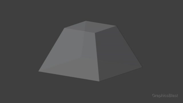
A frustum is the name of the shape you get if you take a pyramid and cut the top off. Specifically so that the new plane at the top is parallel to the plane at the base of the pyramid. Technically a frustum is also the shape if you cut the top off a cone, but in graphics we almost always say it in reference to a pyramidal shape.
Frustums are used a lot in computer graphics to model cameras. In the pin hole camera model, cameras can be imagined as seeing everything within a pyramid emerging from a point in 3D space. However these are problematic to model mathematically close to the camera's centre of projection. As a result, it's easier to instead imagine the camera has a fixed minimum and maximum distance that it can see things within, thereby forming a frustum. This is commonly known as the view frustum. You can read more about these in the section on projection matrices.
Triangulation
Triangulation is the process of converting shapes into triangles. As we mentioned before, a face can be formed of 3 or more vertices. However as GPUs are incredibly optimised for processing triangles, these days they only accept triangles to render. Therefore any incoming data must be converted into triangles. If you have a face of four vertices, it must be converted into a pair of triangles to be rendered, a process known as triangulation.
Any shape can be triangulated. If we have a shape with 5 vertices, labelled A, B, C, D, E, then we can triangulate it in the following way. We lock on to vertex A, and then take the following 2 vertices, so ABC. This is our first triangle. Then from the "two following vertices", we drop the first one, and take the next from our list, so we now have C and D. The next triangle is therefore ACD. Then we just keep doing this until the end of the vertices, so the final triangle will be ADE.
Winding Order
For various reasons, it's helpful to know which is the "front" and the "back" sides of a face or triangle which we are rendering. For example, why bother doing all the calculations to render the back side of a triangle if it won't be visible in our scene? But there are more reasons than just this why it is important to have this distinction.
Let's consider rendering a triangle in 3D space with 3 vertices labelled 1, 2, and 3. From our camera's perspective, if I start at vertex 1 and then go to 2 and then 3, I will either be moving in a clockwise direction or a counter-clockwise direction. In most graphics APIs, if they run in a counter-clockwise direction, they we take that to mean that we are looking at the triangle's "front". We call this a counter-clockwise winding order. Therefore, if we want to make the other side of the triangle the "front", we need to alter the order that we render our vertices in.
Why is counter-clockwise considered the front? Well remember the right-hand rule for rotations. If a triangle's normal vector is facing the camera, then we are looking at it's front. So if you position your right hand where the triangle is, and point your thumb in the direction of the normal, you will your fingers curl in a counter-clockwise direction, so a "positive" rotation should be a counter-clockwise winding in a right-handed coordinate system.
For full information, you can simply adjust the winding order of most APIs, so the clockwise side of every triangle will be the front, but honestly you're probably only going to do this if you've messed up an object's vertex ordering and want to quickly fix it without redoing most of the work. My advice is don't, leave the API's winding order as the default to keep everything else "normal", and fix the winding order of your meshes instead, even if it is more work :)
Normal
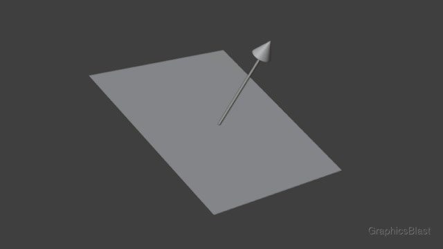
The normal of a face or plane is a directional vector which points perpendicular to it. They are extremely important in computer graphics for calculating lighting.
Let's imagine the floor below us as an example of a plane. A directional vector pointing directly upwards is therefore a normal vector of the floor. The ground also has a second normal pointing directly downwards, although usually in graphics we ignore the second normal vector, and only use the one relevant to the "front" of a face, defined by its winding order.
We can calculate the normal vector of a triangle by taking the cross product of the vector from vertex A to vertex B, and the vector from vertex B to vertex C. Essentially we're taking two of the edges of a triangle, with the cross product of these giving us a vector perpendicular to both of them. The result of the cross product is unlikely to be of length one, so typically we also normalise the result to make it so while maintaining the vector's direction.
Normalise
It is very common in 3D graphics to talk about normalising vectors. When we say this, what we mean is that we want to adjust the vector so that it has a magnitude (length) of exactly 1, without changing the direction it points.
To normalise a vector, we calculate it's magnitude, and then divide each component of our vector by that magnitude. So for the vector (2, 1), we calculate it's magnitude described above, which comes out to 2.24. Then we divide each component by this: (2/2.24, 1/2.24) = (0.89, 0.45). This new vector points in the same direction, but now has a magnitude of 1; it is normalised.
Taking this process a step further, we can make the length of the vector any size we wish, while not affecting its direction or the proportions of each component. If we wish for a vector to have an overall length of 5, we can normalise it to a length of 1 using the above process, and then multiply each component by 5 to reach the desired length.
Homogeneous Coordinates
Homogeneous coordinates are just like regular coordinates - but have an extra dimension which gives them a magical property.
To give a simple example, let's imagine a coordinate in 2D space: (3, 5). To express it in homogeneous coordinates, we first need to decide how it reacts to transformations. Specifically, does it make sense to translate it.
So let's say (3, 5) is being used to represent a directional vector (the direction is an arrow from the origin to (3, 5)). Translating a direction makes no sense, as a directional vector is always from the origin. Translating it would awkwardly alter it's size and the direction it points, which is almost certainly not what we want to do. On the other hand, if (3, 5) represents a vertex, these are completely fine to translate around our scene. If it coordinate can be translated, then we add a one as an extra dimension: (3, 5, 1). If it cannot, a zero: (3, 5, 0).
The same applies in 3D, we extend the length of our vector by one value, either adding a one if we can translate it, else zero.
Then comes the magic: when you then multiply them by a transformation matrix, this final value either "turns on" the translational part of the transformation, or not. We cover the transformation matrices in the next chapter, but essentially the final column of the matrix covers the translation in each axis. By having a zero, when we multiply in the translation, it will therefore also be zero and be ignored, and we only keep the scale, rotation, and skew part of the transformation. If we have a one, then the translation part of the transformation will also be applied.
This means we can multiply everything in our scene, whether vertices or directional vectors, by just a single transformation matrix (efficient!) and whether it should be translated or not is encoded into the coordinates, without any other special caveats or code.
Note that when performing operations on homogeneous coordinates, sometimes you can end up with a different value in the final component. This is normal. You don't have to do anything. You can keep working with them. Just make sure that when converting back to regular coordinates, the final value is either a one or zero.
If it is a direction (ends with 0), then it won't have changed so you don't do anything. But if it's a point (ends with a non-zero value), what you need to do is divide all the other values by this. So if you have (6, 10, 2), it becomes (6/2, 10/2, 2/2) which comes back to our (3, 5, 1). Then, whether it's a one or zero, to get our regular coordinates back, just ignore the final value! This is why it's fine to continue working with them when the final value was not 1: (6, 10, 2) is exactly the same homogeneous point in 2D space as (3, 5, 1)!
Matrix
A matrix is just a 2D grid of numbers. Usually, it is denoted by it's size, for example a 4x4 matrix has 4 rows and 4 columns, and a 2x3 matrix has 2 rows and 3 columns. A vector is just a matrix with only a single column - but we can treat it like any other matrix for mathematical purposes. Matrices are commonly used for transformations in 3D space, and will be used extensively to figure out where each triangle in our scene should be positioned on our screen.
Matrices are one of the core mathematical constructs of 3D graphics, so we'll explore them more in the next chapter.