
Lesson 5: My First Triangle
We now have a window on screen and have had a quick look at what a GPU actually does, so in this lesson we're going to get our hands dirty and actually render something!
In this tutorial we're going to write our first shader programs, and use them to draw our first triangle to the screen. For now we're just going to implement everything in the most simple way possible to give us a feel for the general rendering process and what's involved. We'll not worry too much about error handling and general ease-of-use - we'll cover that in the next lesson!
Overview
So let's have a quick reminder of what we need to do in order to render a triangle with our GPU.
We'll need to write a vertex shader to tell the GPU where to render our triangle in our window, and we'll also need to provide our GPU with a fragment shader to tell it how to colour each pixel of the triangle.
We'll also need to provide our GPU with the triangle's vertex data during initialisation.
Once we have something to render on the GPU and shaders to render it with, we can then make a draw call to the GPU driver.
Introducing GLSL
So how are these shader programs actually written?
To write shader programs, we use a special language called GLSL (GL Shading Language). It's based on C++ and quite similar in many regards, but not exactly the same and is a sort of simplified subset of the language designed to match GPU hardware capabilities and limitations. The language is analogous and fairly similar to HLSL (High-Level Shader Language), which is the DirectX equivalent for performing the same tasks.
Conceptually, when our program starts we'll need to pass the GLSL code to the GPU driver, and ask it to compile the code into a usable shader program. It's up to us how we store our GLSL code. We can hard-code it into our program as a string, but more common is to store the GLSL in a regular text file and read it in when our program starts. The GPU driver will then compile and optimise the GLSL code for the specific GPU architecture of the machine the program is running on, and once it's finished our shader programs will be ready for drawing!
Vertex Shader
Let's see what these shaders actually look like. We'll start with the vertex shader.
As we only want to get a triangle on screen for now, and not dynamically manipulate it's position in any way, our vertex shader is going to be fairly simple. Here's what the GLSL code for it looks like:
| 1. | |
| 2. | |
| 3. | |
| 4. | |
| 5. | |
| 6. | |
| 7. | |
| 8. | |
Hopefully it's not too alien...it is based on C++ after all!
So what's going on here?
We always start our shader programs by writing the version of GLSL on the first line. In fact on some systems it's a hard requirement that line one of any GLSL one must contain this and nothing else! This way we can be sure that any functions we call will be understood by the version of OpenGL our program is running.
Since OpenGL 3.3, the GLSL language version has nicely tracked the version of OpenGL itself.
So for example GLSL version 330 corresponds to OpenGL 3.3, and version 460 as we're using corresponds to OpenGL 4.6.
The "core" profile of the version is assumed by default, but you can also specify that here, for example #version 460 compatibility.
Before our main function, we also need to declare any inputs to our vertex shader.
This is done here with the line layout(location = 0) in vec3 aPosition; - let's break down what this actually does.
The line starts with layout(location = 0), which means that the variable we're declaring will be located in the shader's first buffer (they're zero-indexed!).
The in part of this line then denotes that this is an input variable for our program.
We then have the variable type, which in this case is a vec3, or vector of three elements, or simply an array of three floats.
If you've not seen this mathematical wording before, just remember that a vector is just another word for an array!
Finally we have the name of the variable, aPosition, as it will contain the position of the vertex in 3D space.
The prefix "a" is used here as a reminder that the variable is a vertex attribute - it will be different for every vertex the shader program is run on.
There are other kinds too, like uniform variables which means the GPU can expect the variable to be identical for every vertex drawn.
Differentiating between these kinds of variables allows the GPU to optimise how the memory is laid out.
Our program is now set up to expect to receive an array of 3 floats as an input for each vertex - which will be the vertex's position in 3D space. We can now look at the shader's main function in more detail:
| 5. | |
| 6. | |
| 7. | |
| 8. | |
Like C++, this is the program's entry point. This is fairly straight-forward for now. We take the input position, and set the final rendered position of the vertex to that input, without really modifying it in any way.
We make use of gl_Position, a special GLSL build-in variable, to set the output position of our vertex.
We do however convert our aPosition variable to a vec4 type.
This is because gl_Position expects a homogeneous coordinate.
Essentially, homogeneous coordinates use an extra float variable at the end, where 1 is used to represent points in 3D space, and 0 used to represent directions.
This is really useful when dealing with matrix mathematics, which is why it's used here, and allows your mathematics to not care about whether it's working with directions or positions.
Anyway you don't need to worry about this for now, just remember that a final value of 1 means you're specifying a point in 3D space.
The conversion from vec3 to vec4 is a really nice feature of GLSL and highlights some of the flexibility of the language. We can declare a vec4 array of four floats, and it will figure out that we've passed it a vec3 followed by an individual float (1.0), and use these to initialise the vec4 values.
For now that's all our vertex shader will do. Essentially take the raw triangle vertices and draw them to those coordinates on screen. As it's not doing any 3D manipulation or transformations that's all we need! It might feel like quite a lot of work just to draw a triangle, but remember the key task of these shaders it really for 3D transformations, so for getting a simple 2D triangle it's a bit over-engineered, but it's an important stepping stone for more advanced graphics.
Fragment Shader
Once our triangle's vertices have been passed through the vertex shader, the GPU will rasterise them, and for every pixel which needs to be draw to our window, it will invoke a fragment shader.
For now, no fancy lighting or reflection calculations are being done here. We're just going to say that if this fragment shader is invoked on a pixel, just set the output colour to be orange:
| 1. | |
| 2. | |
| 3. | |
| 4. | |
| 5. | |
| 6. | |
| 7. | |
| 8. | |
Like our vertex shader, we start by defining the GLSL version. We don't have any inputs in this example as we don't need any special data in order to be able to calculate "orange".
We do however declare an output - the pixel's colour. We declare an output of our program named "fragment", where OpenGL assumes the first output if not otherwise specified will be rendered to our window. We declare it as of type "vec4", or a vector of four floats corresponding to the pixel's RGBA values (red, green, blue, and alpha (transparency)).
In the main function of our program, we then set this output pixel equal to a hard-coded set of values. Here, a value of one is the maximum, rather than the more common 255. So this line means the red channel is fully saturated (on), our green channel is about half on, and we have barely any blue. The alpha value of one means the pixel is fully opaque - although this only makes sense if we performing blending in our code, so changing it won't have any effect just yet. So in summary, this program will set the colour of every pixel it is run on to a hard coded orange value, and that's it for now!
Using Our Shaders
Great so we have our GLSL shader source code planned out, let's adjust our main code to actually use these shaders to draw a triangle. Let's begin by laying out a few variables we'll need:
| 15. | bool programRunning = true; |
| 16. | bool isFullscreen = false; |
| 17. | |
| + 18. | |
| 19. | |
| + 20. | |
| + 21. | |
| 22. | |
| 23. | bool init() |
| 24. | { |
We create a variable of type GLuint to act as a handle to our shader program.
Here, GLuint refers to an "uint" or unsigned integer.
As C++ integers can vary in size depending on the machine architecture, which is not great for writing portable APIs, OpenGL defines it's own variable types of fixed size.
Don't worry about this too much though, other than that shader program handles are given to us as GLuint's.
Similarly, we create two variables for holding data about the triangle we'll draw. To do this, we will use two kinds of buffers.
Let's first talk about the Vertex Buffer Object (VBO). The VBO contains any raw data about vertices you wish to draw. These buffers reside on the GPU and can be accessed for drawing extremely quickly. As an example, the coordinates for the vertices for a triangle we wish to draw go into a VBO. But we may also use a VBO to store colour information or texture coordinates as well, and various other bits of data too. It's exactly as the name describes, a buffer (object) to store data about the vertices.
The second kind of buffer we will use is perhaps slightly less intuitively named: the Vertex Array Object (VAO). These store the state of the current buffers. What I mean by this is that if you need to bind three VBOs to draw something, instead of binding each of them every single time you need to draw, you would instead just bind them when setting your program up, and effectively "save" this state of "three bound VBOs" into a VAO.
This means that rather than binding each VBO individually again each time you draw, with all the overhead that involves, you just send one single command to use your VAO and all your buffers will be ready.
Next up, let's update our init function.
First, we'll add the GLSL code for our shaders:
| 86. | if(majorVersion < 4 || (majorVersion == 4 && minorVersion < 6)) |
| 87. | { |
| 88. | printf("Unable to get a recent OpenGL version!\n"); |
| 89. | return false; |
| 90. | } |
| 91. | printf("%s\n", glGetString(GL_VERSION)); |
| 92. | |
| + 93. | |
| + 94. | |
| + 95. | |
| + 96. | |
| + 97. | |
| + 98. | |
| + 99. | |
| + 100. | |
| + 101. | |
| + 102. | |
| + 103. | |
| + 104. | |
| + 105. | |
| + 106. | |
| + 107. | |
| 108. | |
| 109. | ... |
Ehhhhh....multi-line string literals are so ugly in C++.
Don't worry. This is only temporary. In the next lesson we'll switch to reading in our GLSL source code from files instead.
For now, I've simply taken each of our shader's source code from above and stored it as a string literal.
Right, let's create our shader program.
Note that the terminology here can be a little confusing. The OpenGL calls denote a "program" as being the combination of a vertex shader and a fragment shader together. A lot of people though (myself included) sometimes refer to a "vertex shader program". But technically a program is the overall compiled binary composed of both a vertex and a fragment shader.
| 106. | " fragment = vec4(1.0, 0.48, 0.02, 1.0);\n" |
| 107. | "}\n"; |
| 108. | |
| + 109. | |
| + 110. | |
| + 111. | |
| + 112. | |
| + 113. | |
| + 114. | |
| + 115. | |
| 116. | |
| 117. | ... |
We make a call to glCreateProgram which allocates space for a shader program on the GPU and returns us a handle to it.
We store this in the shaderProgram variable we set up earlier.
We then create our vertex shader in the same manner with a call to glCreateShader.
This call requires us to specify what kind of shader we're creating, so we start by going for a vertex shader.
The call to glShaderSource then allows us to set the source code for the shader.
The first parameter is which shader we're setting the source code for.
For flexibility, this function expects to be passed in arrays of strings as the shader source code (in case people wish to pass in their source code line-by-line).
So the next parameter indicates how many strings we're passing OpenGL.
As we have the full vertex source code as a single string, we just pass the number one.
Then the function expects a char** or array of strings.
As we have a char*, passing in the address of our pointer is fine, as the "first" value in the array will be our char* string.
Finally, we pass in the lengths of our strings. If the strings we're passing in are NULL-terminated (which they are), OpenGL allows us just to pass NULL as the string length, and it will keep reading the strings until hitting the NULL character.
Now we've created a vertex shader on the GPU and set the source code for it, we can call glCompileShader to tell the driver to actually compile it.
We finish up by calling glAttachShader to "attach" the vertex shader we created to our shader program.
Next we do the same for the fragment shader:
| 115. | glAttachShader(shaderProgram, vertexShader); |
| 116. | |
| + 117. | |
| + 118. | |
| + 119. | |
| + 120. | |
| + 121. | |
| 122. | |
| 123. | ... |
We create a new shader, this time of type GL_FRAGMENT_SHADER.
We then set it's source code, compile it, and attach it to our shader program just as we did before.
Just like C++ code, after compiling the code, the program needs to be linked together:
| 121. | glAttachShader(shaderProgram, fragmentShader); |
| 122. | |
| + 123. | |
| + 124. | |
| + 125. | |
| + 126. | |
| + 127. | |
| + 128. | |
| 129. | |
| 130. | ... |
The GPU driver takes care of all the work here, so linking the program is just done with a single call.
And with that, our shader program is complete! We're then free to detach and delete each of the shaders. We don't need these objects any more as we already have a compiled and linked executable shader program.
Creating Triangles
Great, so we now have a simple shader program ready to go. We can now define a triangle for it to actually draw:
| 127. | glDetachShader(shaderProgram, fragmentShader); |
| 128. | glDeleteShader(fragmentShader); |
| 129. | |
| + 130. | |
| + 131. | |
| + 132. | |
| + 133. | |
| + 134. | |
| + 135. | |
| 136. | |
| 137. | ... |
These are our triangle's coordinates!
As this data will be passed to the GPU, we've used the OpenGL data-type GLfloat here.
OpenGL types are entirely analogous to regular types C++ types.
For example we can use GLchar and GLint types.
However C++ types are sometimes allowed to vary slightly in size (number of bits). You can imagine the mess if you're passing an int to your GPU where you're CPU thinks an int has 64 bits and your GPU thinks it has 32 bits. Therefore to make the interface with the GPU as simple as possible, OpenGL defines it's own types which are always strictly of a fixed size laid out in the spec. Using these for GPU data is safer, and means casting between types can be done explicitly in our code.
The first row of our coordinates defines the first vertex's x, y and z values. The next line is then the second vertex, and I guess you can figure out the third line.
Until our lesson on cameras, we will be working in screen coordinates - that means they are (almost) just like regular images. The x-axis ranges from -1.0 to 1.0 across the width of your window. If you set a vertex's x value to -1.0, it will be on the left-most part of the window, and +1.0 on the right. Likewise, the second coordinate corresponding to the y value will set the vertical position of the vertex. As you guessed, -1.0 will push it to the bottom of the window, and +1.0 to the top.
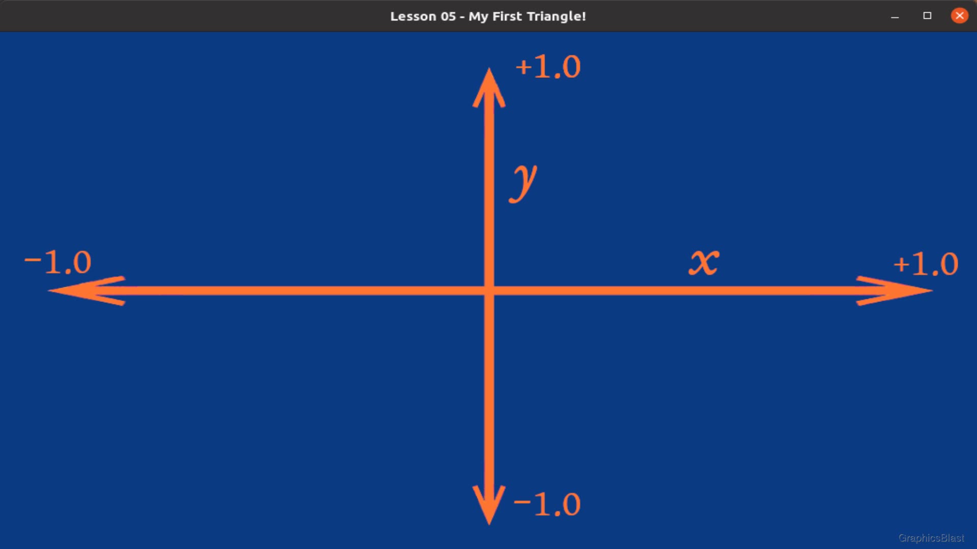
The third float for each vertex is for the z coordinate. This is used to determine the depth of the vertex; things with a greater z will always be drawn behind things with a smaller z value (ie. the distance to the vertex is greater), regardless of the order they were drawn.
I want to stress at this point that this coordinate system is entirely analogous to a 2D image coordinate systems that you may have seen before. The coordinates are normalised (ie. are always between -1 and +1) so you don't have to consider how wide or tall the window is, but otherwise you are practically working on a 2D image.
Let's now create our GPU buffers, and copy our coordinate data in:
| 134. | 0.5f, 0.5f, 0.0f, |
| 135. | }; |
| 136. | |
| + 137. | |
| + 138. | |
| + 139. | |
| + 140. | |
| + 141. | |
| + 142. | |
| 143. | |
| 144. | ... |
The call to glGenVertexArrays generates the actual VAO buffer on the GPU.
Remember, the VAO just remembers which other buffers are bound.
The first parameter of 1 indicates that we only want a single VAO to be created, as this call can actually be used to create an array of VAOs, but for now as we only want to draw a single mesh, we will just use one VAO.
Passing in our vao variable by address in the second parameter effectively makes this an array of one element.
With the VAO created on the GPU, the next line binds it, to make it the current VAO that OpenGL is working with.
Any buffer changes from now on will be remembered by the VAO, until we unbind it.
We then create and bind the VBO, our buffer for storing the vertices. The first line is similar to the VAO, this time generating a buffer on the GPU, and the next line binds it as a vertex array buffer.
However for our VBO, we also make a call to glBufferData which sets the buffer's data - in effect copying our array of vertices from RAM into the VBO in the GPU's memory.
We again let OpenGL know the kind of buffer it is, how much data to copy (in raw bytes, not number of elements!), the actual data itself, and we pass GL_STATIC_DRAW.
The static draw argument it just a hint to OpenGL that we don't plan on modifying this data once it's been set, which the GPU can use to optimise its memory.
Alternatively you can call GL_DYNAMIC_DRAW if you are likely to modify the raw coordinates regularly, although please realise that you can move objects around within a world and perform many fancy effects using the shader, without actually touching these raw coordinates.
Therefore, just to stress this, you almost certainly should leave this as static unless you have good reason to change it.
Now we have our vertices on the GPU, let's finish up...
| 141. | glBindBuffer(GL_ARRAY_BUFFER, vbo); |
| 142. | glBufferData(GL_ARRAY_BUFFER, sizeof(vertices), vertices, GL_STATIC_DRAW); |
| 143. | |
| + 144. | |
| + 145. | |
| + 146. | |
| + 147. | |
| 148. | |
| 149. | glClearColor(0.04f, 0.23f, 0.51f, 1.0f); |
The call to glEnableVertexAttribArray is used to tell OpenGL that the first (hence 0) vertex attribute is in array form.
If you remember back to when we wrote our shader, we bound the input aPosition to location zero.
We also passed in these vertices just above as an array of values which varies for each vertex.
Well, you can also pass in values which are exactly the same for each vertex.
For historical reasons, the latter is the default behaviour, even if it's perhaps less commonly used.
So to pass in our vertices in array form we need to tell OpenGL that for attribute zero (it's position), it should expect an array.
The last thing we need to do is to make a call to glVertexAttribPointer.
Here we explain to OpenGL how exactly the data array of vertices we pass in should be interpreted.
The first value is the buffer index, so the data is to go to location zero in the shader.
Next up, we specify that each vertex is to receive three floats from the array, which will represent our x, y, and z coordinates.
The next parameter defines the data type of our coordinates as floats.
The fourth parameter is quite specific, but determines whether variables should be automatically normalised or not, which we don't want to do.
The fifth parameter, which we set to zero, defines the stride. A stride of zero means the floats we want to use from this data are all right next to each in the array. It could be that our data alternates between a set of spatial vertex coordinates, then a set of texture coordinates, then the next spatial coordinates, and then back to texture coordinates etc. We can therefore use the stride to tell OpenGL to skip a certain number of bytes before reading the next value in the array - but in our case we pass zero as they are all tightly packed into the array.
This raises the question of why would we want to have data inter-twined like this instead of just using another array? Well, perhaps we are loading a 3D model from disk which has data in this format. This way we can just dump it all straight to the GPU and not have to worry about separating the data into separate arrays ourselves. Perhaps more interestingly, there can be speed advantages to this, as all the data for a single vertex is accessed from contiguous GPU memory, which on some architectures may perform better.
The final parameter of this function determines the offset from the start for where to start reading the array, useful if the stride is non-zero. But we just pass a zero to tell OpenGL to start reading our vertex array from the beginning.
We finish up this block of code with a call to glBindVertexArray(0).
This is actually the same call we made a few lines above but passing zero.
Doing so with a value of zero is essentially unbinding our VAO, as we've now finished generating our buffers, passing in the data, explaining to OpenGL how to interpret it, and where it should go in the shader.
Our VBO now holds our vertices on the GPU, and we have set up a VAO which knows to bind a single VBO when drawing.
Before we finish our initialisation code, I just want to add one more thing. Do you remember when I said before that an object with a greater z coordinate have a greater distance from us, the viewer, so will be drawn behind objects closer to us? That's not true. Or at least not right now. By default OpenGL will draw primitives (triangles) in the order your code draws them. We need to explicitly enable depth-testing, in order for the z coordinate to actually be considered when drawing. As it is disabled by default, let's enable it with the following line:
| 149. | glClearColor(0.04f, 0.23f, 0.51f, 1.0f); |
| 150. | |
| + 151. | |
| 152. | |
| 153. | return true; |
| 154. | } |
That's our initialisation done! As we've initialised something, before we go any further, let's not forget to uninitialise it too:
| 156. | void close() |
| 157. | { |
| + 158. | |
| + 159. | |
| + 160. | |
| 161. | |
| 162. | SDL_GL_DestroyContext(context); |
| 163. | SDL_DestroyWindow(window); |
| 164. | SDL_Quit(); |
| 165. | } |
Entirely analogous to the generate buffer calls, we delete the VAO and then the VBO, and finally our shader program when our program closes.
Drawing
With that in place, we can finally get to the last part of this lesson, drawing! Fortunately after all our good work preparing the data, the actual drawing is easy!
| 205. | void draw() |
| 206. | { |
| 207. | glClear(GL_COLOR_BUFFER_BIT | GL_DEPTH_BUFFER_BIT); |
| 208. | |
| + 209. | |
| + 210. | |
| + 211. | |
| + 212. | |
| + 213. | |
| 214. | |
| 215. | SDL_GL_SwapWindow(window); |
| 216. | } |
Every time we draw, we bind our shader, bind our VAO (which in turn sets any states, binds any VBOs etc), and just make a call to glDrawArrays.
This call at long last renders our triangle to our window!
The first parameter of glDrawArrays tells OpenGL what to draw, in this case triangles.
Unfortunately this isn't some parameter where we can tell the GPU to draw squares or pentagons or cars or any other shapes.
It basically amounts to lines, points, and triangles, and some interesting variations on each.
We will go into some of these later, for example GL_TRIANGLE_STRIP for drawing terrains.
The full list can be seen here, but usually you will probably just be using triangles.
The next parameters define which vertex index to start with in the buffer, and the third parameter how many vertices to draw. So this call will draw all three vertices, and make our triangle appear on screen.
Finally, after finishing drawing, we bind a value of zero for our VAO and shader program, in effect unbinding both of these.
TIP: Is it really necessary to unbind everything after use? This applies to shaders/VAOs/VBOs and much more in OpenGL, but let's consider the binding of a shader program. In our code, we continually unbind the shader at the end of every loop only to rebind it again on the next loop. If we removed the unbind, we could still be sure that our triangle is drawn with the correct shader even if our code was much more complex, as we have made sure the correct shader is bound before the draw. The topic is discussed in the comments in this Stack Overflow thread, and the answer essentially boils down to not performing unbinds may be slightly faster, but can lead to undesired corruption if using third-party libraries, so it's considered good practice to follow each bind with a corresponding unbind.
Conclusion
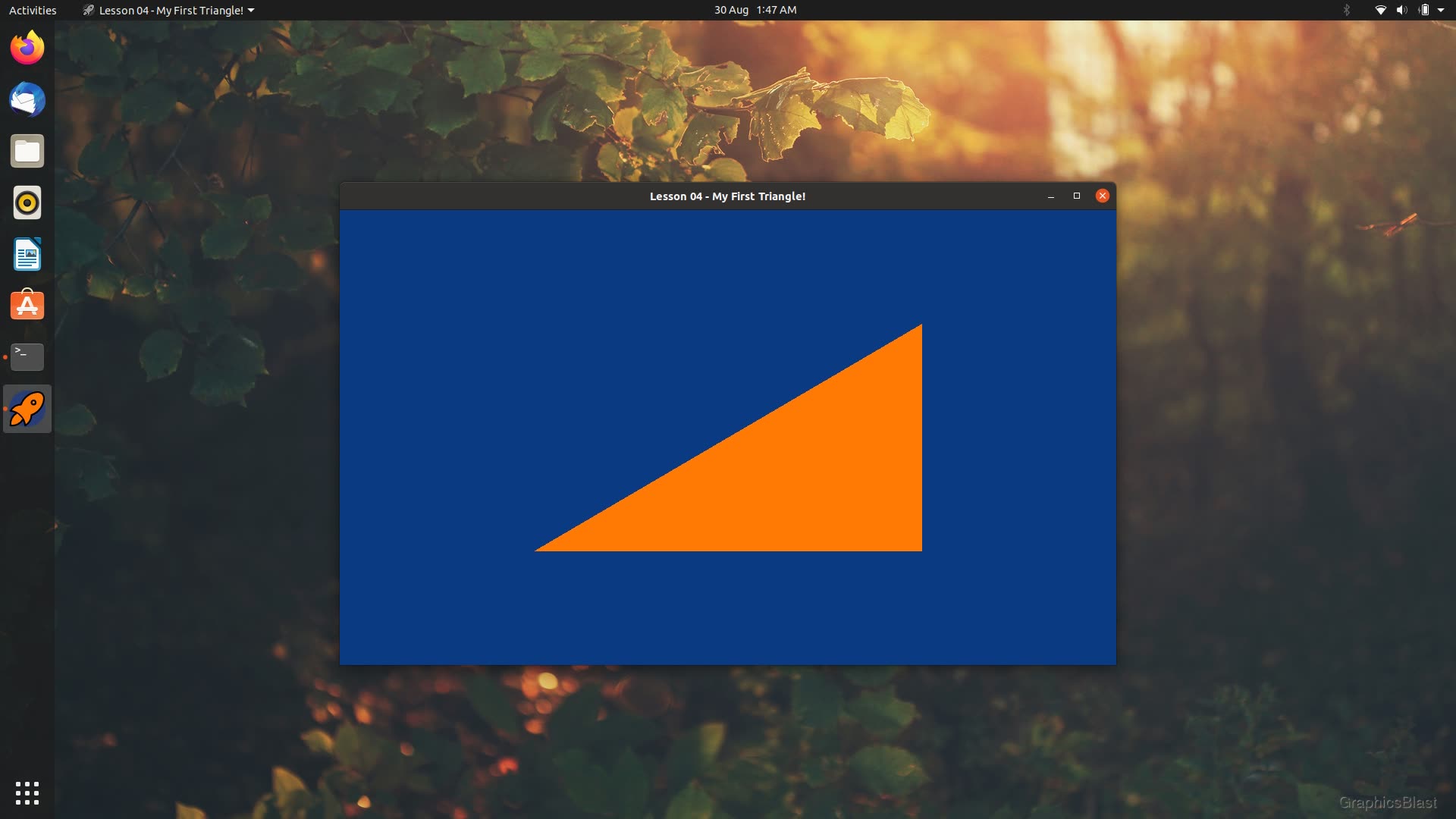
After all that, if you compile and run your code, you should now see your first triangle on screen! Congratulations!
Now, we've covered a huge amount in this tutorial, and I appreciate that much of it may seem superfluous and unnecessary. However, we now have a strong base to build on, and the power of this approach utilising shaders and all this complication will become readily apparent over the next few tutorials.
What's more, we spent lots of time making lots of calls to initialise our GPU buffers. Again, this might seem like we're calling a lot of functions, but essentially it doesn't get much more complicated that that. Creating a buffer, filling it, and telling the shader how to use it for a million triangles is not really any more complex than doing it for a single triangle.
Over the next few lessons, hopefully this way of working will become second nature to you; again you've pretty much seen most of the function calls that even large programs use!