
Lesson 5: Adding Colour
Now that we've got our shaders up and running, in this lesson we'll look at some basic usage of them to blend colours across triangles.
The key idea here is that if each vertex of a triangle has some associated colour value, our fragment shader can interpolate between these to figure out what colour it should set it's pixel to.
In fact, it's even easier. Any output variables of a vertex shader can be read in by the fragment shader. So if our vertices have a colour attribute, and we pass it out of the vertex shader, it is available to be read in by the fragment shader. However the value the fragment shader receives is always automatically interpolated between all three vertices according to how close the fragment is to each vertex.
As it turns out, interpolation is what you need whether you're sending colour data, texture coordinates, or normals for lighting. So if we change our vertex shader code to pass out the colour data it has, and we get our fragment shader to read in the colour value, the fragment shader will only see one value which has automatically been interpolated between each of the vertices.
So that's the theory, let's start by setting up a new buffer to hold the colour data for each vertex, and then pass it in to the vertex shader just as we did for the coordinate data. We'll start by adding a new VBO:
| 20. | Shader mainShader; |
| 21. | |
| 22. | GLuint vao; |
| + 23. | |
| 24. | |
| 25. | bool init() |
| 26. | { |
We change our declaration of our VBO from a single GLuint for the address of a single buffer, to an array of two so we can have one VBO for the coordinates, and one for the colour.
Just as previously we created an array to hold the coordinates of our vertices, we're going to create another to hold the colour (RGB) values of each of those vertices as well. I'm also going to add another set of 3 vertices and 3 colours here so we can look at drawing a second triangle alongside our first one.
| 103. | GLfloat vertices[] = |
| 104. | { |
| 105. | -0.5f, -0.5f, 0.0f, |
| 106. | 0.5f, -0.5f, 0.0f, |
| 107. | 0.5f, 0.5f, 0.0f, |
| + 108. | |
| + 109. | |
| + 110. | |
| 111. | }; |
| 112. | |
| + 113. | |
| + 114. | |
| + 115. | |
| + 116. | |
| + 117. | |
| + 118. | |
| + 119. | |
| + 120. | |
| + 121. | |
So we have the original 3 vertices of our first triangle, and then another 3 for the second triangle. We then have 6 RGB values, each holding the colour of the corresponding vertex. So the first line of RGB values set the colour of the first vertex. Again these values range from 0 to a maximum of 1.
Just like with our coordinate data, we need to upload it to a GPU buffer. But we also need to modify our previous code slightly as now we have an array of VBOs.
So we need to update our call to glGenBuffers to this time request two buffers be created.
| 123. | glGenVertexArrays(1, &vao); |
| 124. | glBindVertexArray(vao); |
| 125. | |
| + 126. | |
| 127. | |
| + 128. | |
| 129. | glBufferData(GL_ARRAY_BUFFER, sizeof(vertices), vertices, GL_STATIC_DRAW); |
As we are now passing an array value, as the call expects, we no longer need to pass by address.
We also change our bind buffer call for the vertices, so instead of binding vbo, we only bind the first buffer in the array, vbo[0].
Creating the colour VBO on the GPU is then exactly as we did for the coordinates:
| 128. | glBindBuffer(GL_ARRAY_BUFFER, vbo[0]); |
| 129. | glBufferData(GL_ARRAY_BUFFER, sizeof(vertices), vertices, GL_STATIC_DRAW); |
| 130. | |
| 131. | glEnableVertexAttribArray(0); |
| 132. | glVertexAttribPointer(0, 3, GL_FLOAT, GL_FALSE, 0, 0); |
| 133. | |
| + 134. | |
| + 135. | |
| + 136. | |
| + 137. | |
| + 138. | |
| 139. | |
| 140. | glBindVertexArray(0); |
We bind the second buffer, and this time upload the colours data to this buffer.
We also enable it as an array, as we're (obviously) feeding it with an array. This time though as it will go to the shader's second input location, we enable the second (1) location as being array based.
The final line then indicates to OpenGL how to distribute our colour values array to the shaders.
The shader's input location 1 should receive 3 floats each from the array per vertex.
Again the final 3 parameters say the data should not be normalised, there is no stride in the data, and no starting offset, just as we discussed when setting up the first VBO.
We then need to clean up our new buffers at the end:
| 149. | void close() |
| 150. | { |
| 151. | glDeleteVertexArrays(1, &vao); |
| + 152. | |
| 153. | mainShader.deleteShader(); |
| 154. | |
| 155. | SDL_GL_DestroyContext(context); |
| 156. | SDL_DestroyWindow(window); |
| 157. | SDL_Quit(); |
| 158. | } |
We update our call to glDeleteBuffers to delete 2 buffers from our array, and again as we are now passing in an array we can remove the ampersand on our vbo variable.
OK so we now have our extra VBO containing the colour information set up on the GPU and tidied up correctly when the program finishes. Just before we update our shaders to use this new data, let's update our draw call to include the extra triangle:
| 207. | void draw() |
| 208. | { |
| 209. | glClear(GL_COLOR_BUFFER_BIT | GL_DEPTH_BUFFER_BIT); |
| 210. | |
| 211. | mainShader.bind(); |
| 212. | glBindVertexArray(vao); |
| + 213. | |
| 214. | glBindVertexArray(0); |
| 215. | mainShader.unbind(); |
| 216. | |
| 217. | SDL_GL_SwapWindow(window); |
| 218. | } |
The update to glDrawArrays tells OpenGL that it now needs to draw 6 vertices, which as we're drawing triangles means two full triangles will appear on screen.
Again the zero value indicates that OpenGL should start reading the buffers from the beginning, so starting with our first vertex onwards until there are 6 in total.
So that's our main code updated. If we run it as it is, our code will push additional vertex data to the GPU, and draw it, so we'll now see two triangles forming a square.
Even though we've pushed the additional colour data too, into shader input location 1, our shaders are not currently making use of it, so our square will just be orange from the previous shader code. We'll update that next.
Shading with colour
So we've passed new data into the GPUs rendering pipeline. The first place it will get to is the vertex shader, with an RGB value for each vertex. Currently the colour data reaches there, and is never used or passed on further into the pipeline. Let's update that:
| 1. | #version 460 |
| 2. | |
| 3. | layout(location = 0) in vec3 aPosition; |
| + 4. | |
| 5. | |
| + 6. | |
| 7. | |
| 8. | void main() |
| 9. | { |
| + 10. | |
| 11. | gl_Position = vec4(aPosition, 1.0); |
| 12. | } |
We add a new input to our vertex shader to receive the colour information associated with the vertex.
This reads from location 1, which is where we sent the colour information too in our main.cpp.
It's an input, so we specify in and it's an array (vector) of three values, so we can use the vec3 data-type again.
Finally, as it's a vertex attribute, meaning it has a different value for each vertex, by convention we prefix the name with an "a".
We also declare an output variable for the vertex shader, named colour.
Again this is of vec3 type, and because it's defined as an output (out) it will be passed down the GPU's rendering pipeline and make it's way into the fragment shader.
In the main function of our vertex shader, we simply take our input colour for the vertex, and pass it to the shader output. That's pretty much it - the variable is just passed through this pipeline stage.
So how does our fragment shader look now?
| 1. | #version 460 |
| 2. | |
| + 3. | |
| 4. | |
| 5. | out vec4 fragment; |
| 6. | |
| 7. | void main() |
| 8. | { |
| + 9. | |
| 10. | } |
It's not too bad, right?
So how does this work? As we spoke about before, OpenGL will calculate that the current triangle being rendered will cover a certain set of pixels on screen, and then run this shader for each of those pixels to decide what colour they should be (this process is known as rasterisation).
As these pixels will be somewhere inside the triangle (or on the triangle's edges), they need to decide which vertex they should use to get their colour input from.
What they do is to take all three of the vertex shader outputs and interpolate them based on how close the pixel is to each vertex.
This means that the colour input variable our fragment shader receives has already been interpolated for us!
It might seem like an odd choice at first, to interpolate the variables from each of the vertex shaders. Why not just take the value from the closest vertex for example. But as you will discover through the next few lessons, this kind of interpolation is pretty much exactly what you want for any kind of complex light rendering or special graphical effects on screen.
This triangular interpolation process is known as barycentric interpolation. If a pixel lies exactly on a vertex, it will take the value only from that vertex, and as it get close to the opposite edge of the triangle, this influence will reduce to zero. It the pixel lies exactly half way between two vertices, it's colour will therefore be halfway between the values of these two vertices. In the centre of the triangle, it will have equal weighting of all three vertices.
Looking back to our code, our fragment shader receives the colour variable as an input, which has already been automatically interpolated between the 3 colour outputs of the triangle's three vertices.
In our main function, we simply plug the vec3 into our vec4 colour output, therefore setting the pixel's colour to the interpolated value.
So that's all we have to do to add colour to our triangles!
Conclusion
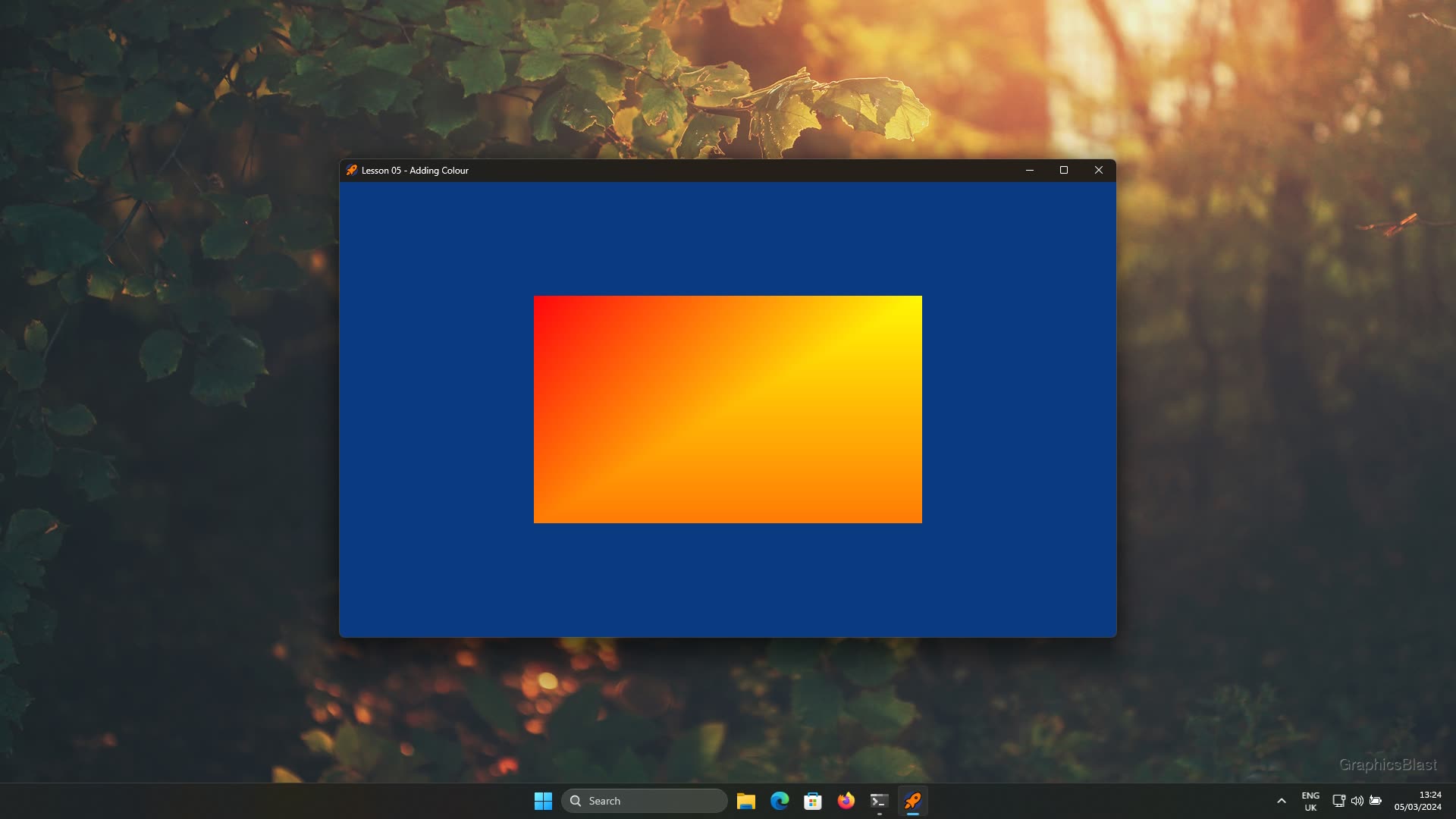
With the shaders in place, that should be everything! Compile and run your code, and you should see a pair of triangles forming a square in our window. The fragment shader program is being run for each pixel of our triangles, and should be interpolating between the vertices to set the colour. You should see some lovely (or not, depending on taste) blended colours in front of you.
If you look very closely, you may see some interpolation artefacts along the diagonal of our square. The reason for this is that the interpolation only occurs within the triangle being rendered, and any other triangle's colour data is therefore not taken into account. If that other triangle has a much more intense colour gradient, there will be a seam along the two triangle's shared edge. Each triangle is correctly rendered, it's just that our eyes expect the colours to fade gradually over the entire square, not just within sections of it.
While here it isn't so visible, if you make one triangle a much different size to the other, and use more extreme colours, it will be much more visible. Don't worry about this though, this is a natural artefact of the GPU rendering pipeline, and is only really visible when rendering raw colours. For real rendering, the effect should disappear. I just wanted to mention somewhere here though that this does exist!
Anyway, that's all. In the next lesson we'll look at using index buffer objects to re-use vertex data, and wireframe mode! See you there!